A Large Step Ahead: Conserving Natural Resources, Exploiting Economic Opportunities
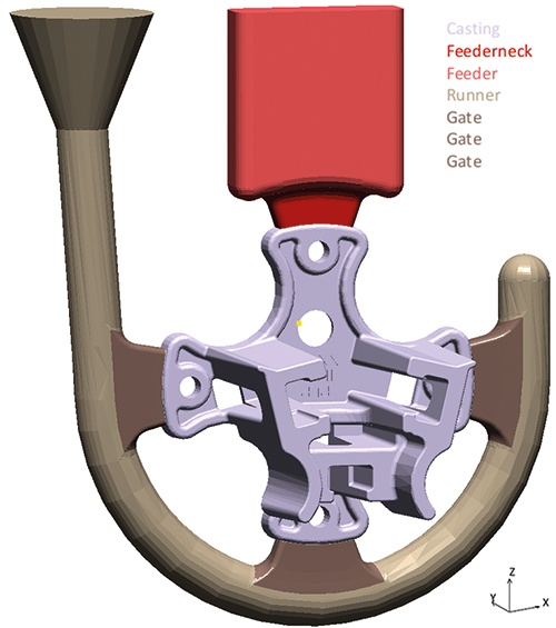
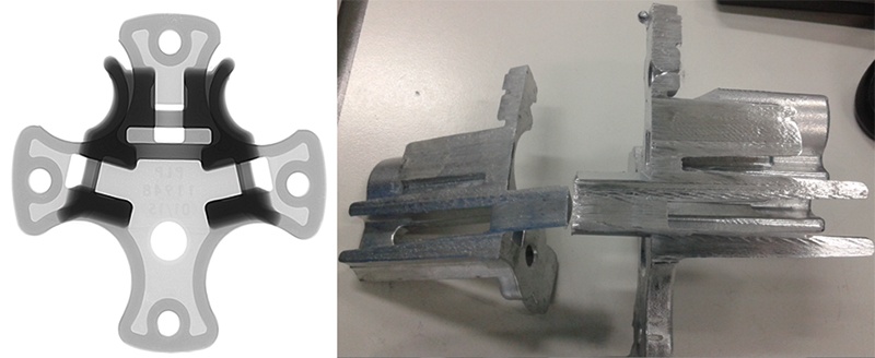
The journey was long, the goal well known. From the initial idea of the product through production-ready development to manufacturing – before getting to the final step, the foundry had to identify potential problems and solve them adequately. First of all: The casting had quite a complex shape with a mixture of thickwall sections and a long thin cross section. For the manufacturing process, PLP Indonesia had two different options in mind: permanent mold or die casting. Since the part was new, they forecast a low demand for the first few years. Because only a small quantity was planned for production, the HPDC process was considered not suitable (more costly and time-consuming in this case). The decision was taken to manufacture the “Clamp Base” part (Fig. 1) using the gravity die casting process with a vertical parting line as layout for the gating system.
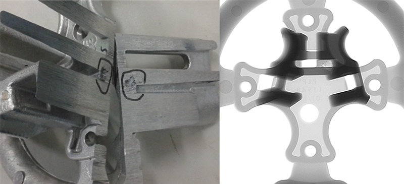
However, already during the initial production stage, shrinkage porosity was detected (Fig. 2). This casting defect resulted in a high scrap rate, yet the production capacity was sufficient to meet the low demand.
A Product in High Demand
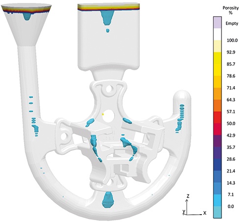
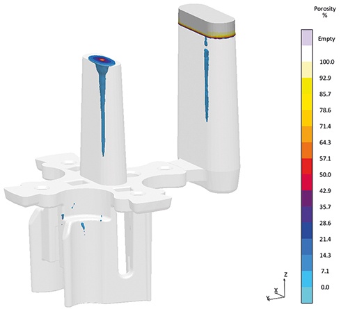
Suddenly, everything happened very quickly: The demand for the “Clamp Base” component increased considerably. PLP Indonesia had to react immediately to prevent the current scrap rate from compromising the further production. MAGMASOFT® was used to simulate the original design of the casting to compare the actual casting defect with the simulation results and fully understand the root cause of the defect. Simulation results (Fig. 3) showed a good correlation with the observed shrinkage porosity (Fig. 2).
Virtual Design of Experiments (DoE)
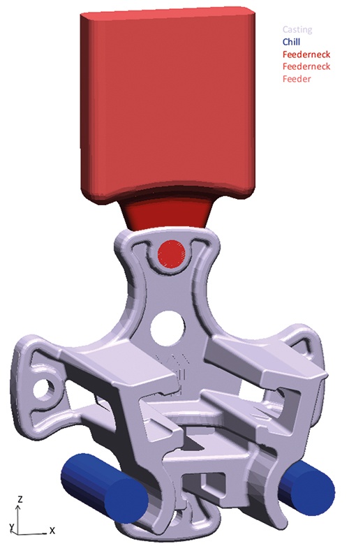
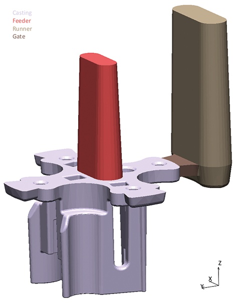
With this good basis, a virtual design of experiments (DoE) was set up in MAGMASOFT® to reduce both the shrinkage porosity (‘Porosity’) and the hot spots (‘Hot Spot’). The only parameters that could be modified were the feeder dimensions, additional machining allowances, and the use of copper inserts in the mold to influence the local cooling rate. Fig. 4 illustrates the selected geometry for the virtual experimental design.
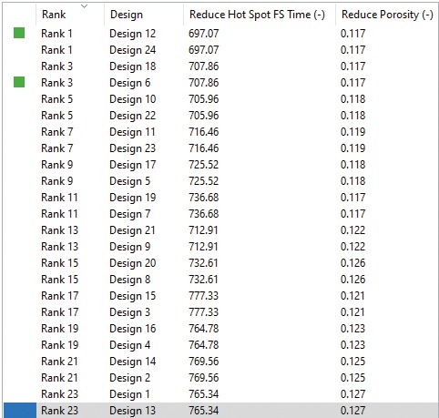
Although the variation of the above parameters resulted in reduced shrinkage porosity and hot spots, it was not possible to eliminate the shrinkage porosity. The overview table (see Fig. 5) shows that even the best design, ranking first (‘Rank 1’), still has shrinkage porosity in the casting.
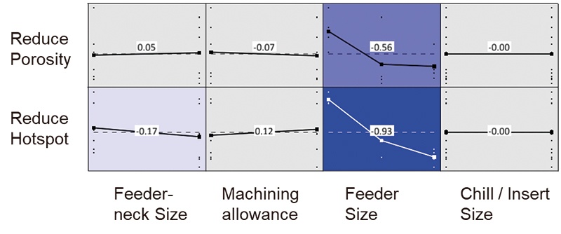
The use of virtual design of experiments allows simultaneously analyzing the effect of selected parameters on the casting to ensure a sound and robust production. Fig. 6 summarizes the results for this example in a correlation matrix. This methodology helped PLP Indonesia to find out which variables have a significant influence on quality criteria. For the investigated component, the feeder size had a significant influence on the reduction of porosity (dark blue color in Fig. 6). In contrast, the machining allowance or the copper inserts had no significant influence on the pre-defined objectives (gray background in Fig. 6).
Goal Achieved?
As the possible changes in parameters, especially the size of the feeder, could not provide the desired solution of a porosity-free part, PLP Indonesia thought: “Just be creative.” One idea to solve the casting defect was to change the mold parting line from vertical to horizontal (Fig. 7).
At that time, the company did not yet have equipment that would allow the use of a horizontal parting line in production. After many internal discussions, PLP Indonesia nevertheless agreed to the proposal, among others, based on the positive MAGMASOFT® result for this layout (Fig. 8). Therefore, a new platform for the current gravity die casting machine was designed to adopt the horizontal design in production.
PLP Indonesia made the right decision: The new layout resulted in a significant improvement over the original design. The result was a good quality of the castings (Fig. 9). In addition, the overall scrap rate was reduced to below 3 %.
Defects that still occurred resulted from deficiencies in the process. PLP Indonesia measured the temperature in the furnace before they started pouring. With the new set-up, the distance between the furnace and the mold increased, leading to a significant, uncontrolled temperature drop of the melt before the start of casting. This led to fluctuations in the process and was the reason for the previously mentioned still occurring casting defects. Using MAGMASOFT® not only allowed analyzing these process fluctuations but also identified them as the root cause of the occurring casting defects.
In the future, PLP Indonesia will consider these process fluctuations at an early stage for laying out new casting designs and casting processes, to thus identify critical process conditions as well as the main causes of potential casting defects.
All in all, useful experience that will be remembered when analyzing further castings. Having reached the desired goal for the “Clamp Base” component, the journey for PLP Indonesia with MAGMASOFT® is still far from over. The next project is already in the pipeline.
About Preformed Line Products (PLP Indonesia)
Preformed Line Products (PLP Indonesia) is a global designer, manufacturer and supplier of high quality cable anchoring and control hardware. With pioneering and innovative solutions, such as COYOTE® fiber optic products and the THERMOLIGN® family of power transmission products, PLP has consistently pioneered modern advances in communications and power networks since 1947.
